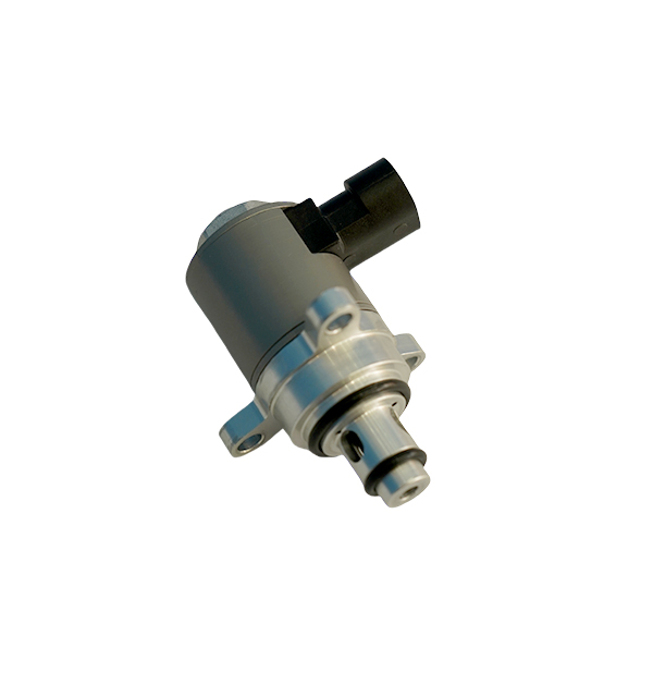
Specific Operation Steps for Installing Exhaust Valves
I. Pre-Installation Preparations
Equipment and Material Inspection
Verify the exhaust valve model, specification (e.g., DN25-DN100), rated pressure (PN16-PN40), and applicable medium (gas/steam/liquid) to ensure consistency with design drawings.
Inspect the valve body for cracks or sand holes, check that the bonnet and seat sealing surfaces are flat, and test the opening/closing mechanism for flexibility (manually operate 3–5 times).
Prepare tools: wrenches, spirit levels, pressure gauges, PTFE tape, sealant (e.g., Loctite 598), and pipeline cleaners.
Pipeline Pre-Treatment
Flush the pipeline interior with compressed air (0.6–0.8MPa) or high-pressure water to remove welding slag, rust, and debris; use an endoscope for cleanliness inspection if necessary.
Measure the outer diameter of the pipeline at the installation site to ensure compatibility with the exhaust valve interface (e.g., thread-to-pipe diameter matching for threaded connections).
II. Installation Location Determination
Optimal Position Selection
Install at the highest point of the pipeline or equipment (e.g., the top of heat exchangers, the apex of U-shaped pipes) to facilitate gas discharge.
Maintain upstream straight pipe length ≥10D and downstream ≥5D (D = pipeline diameter) to avoid installing near elbows or reducers that cause flow turbulence.
Height and Accessibility Control
Ensure ≥500mm of clearance around the valve for easy operation; install a maintenance platform if the installation height exceeds 2m.
In cold regions, position valves away from direct exposure to rain/snow; allow ≥300mm space for subsequent thermal insulation.
III. Installation Process
Threaded Connection Installation
Step 1: Thread Preparation
Apply 3–4 layers of PTFE tape clockwise on the pipe threads, starting 1–2 threads from the end to prevent tape from entering the pipeline.
Step 2: Valve Alignment
Align the exhaust valve's flow direction mark (if any) with the pipeline flow; for non-directional valves, ensure the stem is vertical (deviation ≤1°).

Step 3: Tightening
Hand-tighten the valve until it seats, then use a wrench to turn an additional 1–1.5 turns (torque reference: 15–20N·m for DN25 valves). Avoid over-tightening to prevent thread damage.
Flanged Connection Installation
Step 1: Gasket Placement
Position the gasket (e.g., spiral wound for high pressure) centered on the flange, ensuring it does not protrude into the pipeline bore.
Step 2: Bolt Installation
Insert bolts through the flange holes symmetrically, hand-tightening all bolts first to align the flanges.
Step 3: Torque Tightening
Tighten bolts in a cross pattern (e.g., star sequence) in 2–3 stages, reaching the specified torque (e.g., 40–50N·m for M12 bolts on PN16 flanges).
IV. Protection Device Installation
Upstream Filter Setup
Install a 40–60μm mesh Y-strainer 3–5D upstream of the exhaust valve, ensuring the filter's flow direction matches the pipeline. Tighten the filter cover with a torque wrench (e.g., 25–30N·m for DN50 filters).
Anti-Freeze Measures (for Cold Environments)
Wrap electric tracing tape (power ≥20W/m) around the valve body and adjacent pipelines, covering with 50mm-thick thermal insulation (e.g., glass wool) and an aluminum protective shell.
V. Leakage and Function Testing
Hydrostatic Pressure Test
Close the exhaust valve, apply 1.5× rated pressure (e.g., 1.5MPa for PN10 valves) to the pipeline, and hold for 15 minutes. Check for leakage at joints using soapy water (allowable bubbles ≤5 per minute for DN50 valves).
Air Discharge Function Test
Slowly pressurize the system to 1.05× operating pressure, observing that the exhaust valve opens to release gas smoothly. When liquid approaches, the valve should close automatically without continuous flow (verified by water injection testing).
Vacuum Resistance Test (for Vacuum Systems)
Create a vacuum of -0.08MPa in the pipeline; the exhaust valve's check mechanism should prevent outside air from entering (monitored by a vacuum gauge, pressure rise ≤0.005MPa/h).
VI. Post-Installation Finishing
Marking and Documentation
Label the valve with its number, medium flow direction, and opening/closing status indicator.
Record installation parameters (torque values, test pressures, dates) in a maintenance log.
System Integration Check
Recheck all connections for tightness, ensuring no tools or debris are left in the work area.
For steam systems, perform a 2-hour warm-up run to eliminate thermal expansion stresses, retightening bolts after cooling.
VII. Safety and Compliance Notes
Gas System Precautions: Use explosion-proof tools for natural gas pipelines, grounding the valve body (resistance ≤4Ω) to prevent static discharge.
Food Industry Requirements: Install 316L stainless steel exhaust valves with electropolished surfaces (Ra ≤0.8μm), compliant with 3-A Sanitary Standards.
Pressure Vessel Compliance: Ensure valves used in pressure vessels meet ASME BPVC Section VIII or GB 150 standards, with factory pressure test reports.
Following these steps ensures proper exhaust valve installation, enabling efficient gas discharge, preventing system cavitation, and maintaining operational safety.
